In this tutorial, you will create a ball bounce animation using various animation techniques.
This Blog serves as an additional learning resource for "The Autodesk Maya Books. It contains latest tutorials, articles, views, reviews, and tips & tricks on Autodesk Maya - A CADCIM Technologies, USA Initiative
Thursday, December 12, 2013
mt004 - Creating a ball bounce animation
Thursday, August 8, 2013
mt003 - How to create a realistic Light Lamp in Maya?
In this tutorial, we will walk you through the process of creating believable Lamplight using Maya. To give lamp realistic effect we just can't put a single point light in the middle but we have to use multiple lights with different settings to produce the result we are looking for.
As you can see in image below we have used one directional Light for fill light and five points light for flames. Point lights provide illumination to the flames while one directional light fills the dark area of the scene.
As you can see in image below we have used one directional Light for fill light and five points light for flames. Point lights provide illumination to the flames while one directional light fills the dark area of the scene.
Wednesday, May 29, 2013
Autodesk Maya 2014 book by CADCIM Technologies
Welcome to the world of Autodesk Maya 2014. Autodesk Maya 2014 is a powerful, integrated 3D modeling, animation, visual effects, and rendering software developed by Autodesk Inc. This integrated node based 3D software finds its application in developing films, games, and design projects. A wide range of 3D visual effects, computer graphics, and character animation tools make it an ideal platform for 3D artists. The intuitive user interface and workflow tools of Maya 2014 have made the job of design visualization specialists a lot easier.
Autodesk Maya 2014 book covers all features of Autodesk Maya 2014 in a simple, lucid, and comprehensive manner. It aims at harnessing the power of Autodesk Maya 2014 for 3D and visual effects artists and designers. This textbook will help you transform your imagination into reality with ease. Also, it will unleash your creativity, thus helping you create realistic 3D models, animation, and visual effects. It caters to the needs of both the novice and advanced users of Maya 2014 and is ideally suited for learning at your convenience and at your pace.
Table of Contents
Chapter 1
Exploring Maya Interface
Chapter 2
Polygon Modeling
Chapter 3
NURBS Curves and Surfaces
Chapter 4
NURBS Modeling
Chapter 5
UV Mapping
Chapter 6
Shading and Texturing
Chapter 7
Lighting
Chapter 8
Animation - I
Chapter 9
Animation - II
Chapter 10
Paint Effects
Chapter 11
Rendering
Chapter 12
Particle System
Chapter 13
Introduction to nParticles
Chapter 14
Fluids
Chapter 15
nHair
Chapter 16
Maya Fur
Chapter 17
Bullet Physics
Pre-Order Now
Tuesday, May 7, 2013
mt0002 - Creating an arm chair in Maya 2014
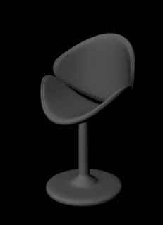
In this tutorial, you will create an arm chair using the polygon modeling techniques using Maya 2014, as shown in Figure t2-1.
Start a new scene in Maya 2014.
Step -2
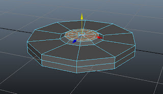
Choose Create > Polygon Primitives > Cylinder > Option Box from the menubar; the Tool Settings (Polygon Cylinder Tool) window is displayed in the viewport, enter 10, 2 and 1 in the Axis divisions, Height divisions and Cap divisions edit boxes, respectively, as shown in Figure t2-2.
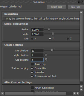 |
Figure t2-2 The Tool Settings (Polygon
Cylinder Tool) window |
Step -3
Click on the viewport; pCylinder1 is displayed in it, as shown in Figure t2-3.
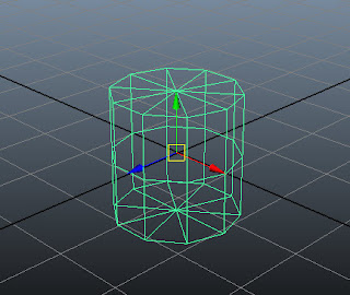 |
| Figure t2-3 The cylinder displayed in the viewport |
Step - 4
Choose Shading > Smooth Shade All from the Panel menu or press 5; pCylinder1 is displayed in the shaded mode.
Step - 5
Rename pCylinder1 as base in the Channel Box / Layer Editor.
Step - 6
Hover the cursor on the persp viewport and then press SPACEBAR; the four viewports are displayed. Next, maximize the front viewport.
Step - 7
Select base. Next, choose Scale Tool from the tool box or press R.
Step - 8
Uniformly scale down the base, as shown in Figure t2-4.
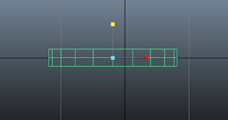 |
| Figure t2-4 Base scaled down |
Step - 9
Hover the cursor on the front viewport and then press SPACEBAR; the four viewports are displayed. Maximize the persp viewport.
Step - 10
In the persp viewport, press and hold the right mouse button on base; a marking menu is displayed. Next, choose Face from the marking menu.
Step - 11
Now, select the top faces of base using the SHIFT key, as shown in Figure t2-5. Next, choose Edit Mesh > Extrude from the menubar.
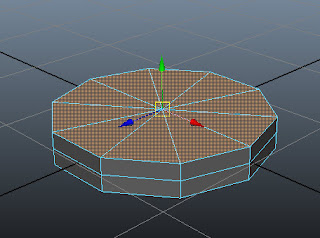 |
| Figure t2-5 Top faces of the base selected |
Step - 12
Invoke Scale Tool and scale down the selected faces uniformly, as shown in Figure t2-6.
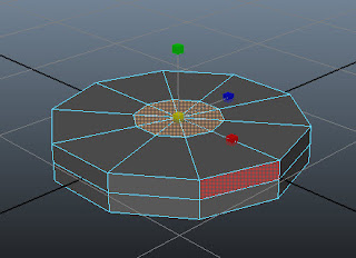 |
| Figure t2-6 The top faces of the base scaled down uniformly |
Step - 13
Press G key to invoke the Extrude command again. Next, invoke the Scale Tool by pressing R key and then scale down the selected faces uniformly, as shown in Figure t2-7.
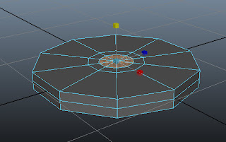 |
| Figure t2-7 The selected faces of the base scaled down uniformly |
Step - 14
Choose Edit Mesh > Insert Edge Loop Tool from the menubar. Next, click on top region of the base; an edge is inserted, refer Figure t2-8. Press W to deactivate the Insert Edge Loop Tool.
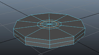 |
| Figure t2-8 An edge inserted at the top of the base |
Step - 15
Press and hold the right mouse button; a marking menu is displayed. Next, choose Face from the marking menu. Select the faces of base using SHIFT, as shown in Figure t2-9.
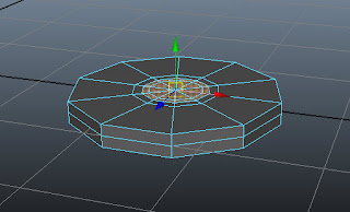 |
| Figure t2-9 Faces of the base selected |
Step - 16
Next, move the seleced faces upward,
as shown in Figure t2-10.
Step
- 17
Step -20
Deselect the outer selected faces using
SHIFT and then move upward, as shown in Figure t2-11.
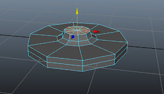 |
| Figure t2-11 Outer faces moved upward |
Step - 18
Hover the cursor on the persp viewport. Press SPACEBAR; the four viewports are displayed. Maximize the
front viewport.
Step
- 19
Press 5 to switch to the shaded mode. Choose Edit Mesh > Extrude from
the menubar. Next, invoke Move Tool and
then move the extruded faces upward, as shown in Figure t2-12.
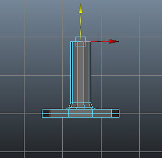 |
| Figure t2-12 Extruded faces moved upward |
Press and hold the right mouse button
on base; a marking menu is displayed. Next, choose Object Mode and then select the base.
Step - 21
Make sure base is selected in the front viewport. Choose Mesh > Smooth > Option Box from the
menubar; the Smooth Options dialog
box is displayed. In this dialog box, make sure the Division
levels slider is set to 2. Now, choose the Smooth button; the geometry of base is smoothened, as shown in
Figure t2-13.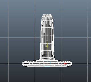 |
| Figure t2-13 The smooth base displayed |
Step - 22
Press and hold the right mouse button on the base; a marking menu is displayed. Next, choose vertex from
the marking menu and then select the vertices, as shown in Figure t2-14.
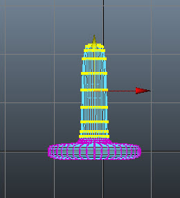 |
| Figure t2-14 Vertices selected |
Step - 23
Next, invoke the Scale Tool by pressing R
key and scale the selected faces uniformly, as shown in Figure t2-15.
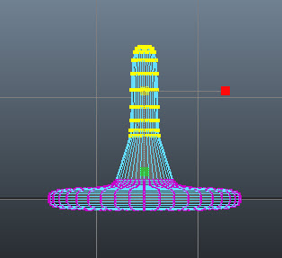 |
| Figure t2-15 Selected vertices scaled uniformly |
Step - 24
Now, scale the selected vertices downward, as shown in Figure t2-16. Switch to the object mode.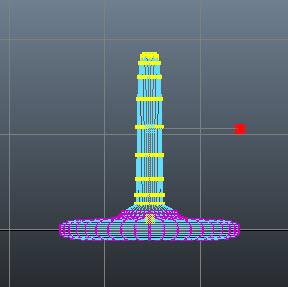 |
| Figure t2-16 Selected vertices scaled downward |
Step - 25
Hover the cursor on the front viewport. Press SPACEBAR; the four viewports are displayed. Maximize the persp viewport. Next, choose Create > Polygon Primitives > Cube > Option Box from the menubar; the Tool Settings (Polygon Cube Tool) window is displayed in the viewport, enter 5, 2 and 3 in the Width divisions, Height divisions and Depth divisions edit boxes, respectively, as shown in Figure t2-17. Next, enter 1,0.5 and 0.5 in the Width, Height and Depth edit boxes, respectively, refer to Figure t2-17.
 |
Figure t2-17 The Tool Settings (Polygon
Cylinder Tool) window |
Step - 26
Click on the persp viewport; pCube1 is displayed in the viewport, as shown in Figure t2-18.
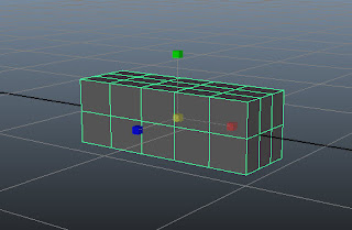 |
| Figure t2-18 The cube displayed in the viewport |
Step - 27
Rename pCube1 as seat in the Channel Box / Layer Editor.
Step - 28
Maximize the front viewport. Scale the seat along the X and Y axis, as shown in Figure t2-19.
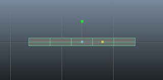 |
| Figure t2-19 The scaled seat |
Step - 29
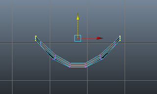
Press and hold the right mouse button on it; a marking menu is displayed. Choose vertex from the marking menu. Now, select the vertices, as shown in Figure t2-20.
 |
| Figure t2-20 Vertices to be selected |
Step - 30
Choose the Move Tool. Now, adjust the selected vertices, as shown in Figure t2-21.
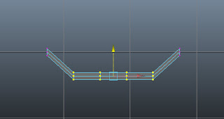 |
| Figure t2-21 Selected vertices adjusted |
Step - 31
Similarly, adjust other vertices to create the basic shape of seat, as shown in Figure t2-22
Step - 32
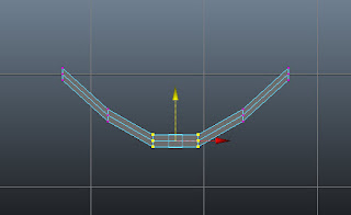 |
| Figure t2-22 Other vertices adjusted |
Maximize the top viewport and then select the vertices as shown in Figure t2-23a. Choose Scale Tool and then scale the selected vertices along the Z-axis, as shown in Figure t2-23b.
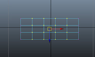 |
| Figure t2-23a The vertices to be selected |
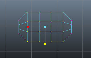 |
| Figure t2-23b The selected vertices scaled |
Step - 33
Similarly, scale other vertices, as shown in Figure t2-24.
 |
| Figure t2-24 Other selected vertices scaled down |
Step - 34
Select the vertices, as shown in Figure t2-25a. Next, scale the selected vertices along the X-axis, as shown in Figure t2-25b.
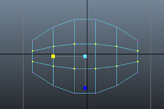 |
| Figure t2-25a Vertices to be selected |
 |
| Figure t2-25b New selected vertices scaled left |
Step - 35
Maximize front viewport. Choose the Move Tool. Now, select the vertices, as shown in Figure t2-26a and then adjust the selected vertices, as shown in Figure t2-26b.
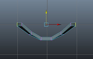 |
| Figure t2-26a Vertices to be selected |
Press and hold the right mouse button on it; a marking menu is displayed. Next, choose Object Mode from the marking menu and then select seat.
Step - 37
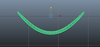
Choose Mesh > Smooth from the menubar; the mesh of seat is smoothened.
Figure t2-27 shows the seat after smoothing.
Next, press CTRL + D; a duplicate copy of the seat is created with the name seat1 in the viewport.
Step - 39
Choose Rotate Tool from the Tool Box or press E. Now, enter 90 in the Rotate X edit box in the Channel Box/Layer Editor; seat1 is rotated 90 degrees about the X-axis.
Step - 40
Next, choose the Move Tool and then align seat1 in all viewports, as shown in Figure t2-28.
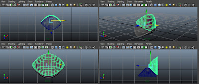 |
| Figure t2-28 Copied object aligned in all viewports |
Step - 41
Maximize the persp viewport. Press and hold the SHIFT key and select seat. Next, press CTRL + D; a duplicate copy of the selected objects are created in the viewport, as shown in Figure t2-29.
Step - 42
Next, invoke the Scale Tool by pressing R key and scale down uniformly, as shown in Figure t2-30.
Step - 43
Invoke Move Tool by pressing W key. Next, maximise the front viewport. Press and hold the SHIFT key and select seat and seat1. Now, align the selected parts, as shown in figure t2-31.
Step - 44
Maximize the persp viewport. Press and hold the SHIFT key and select seat. Next, press CTRL + D; a duplicate copy of the selected objects are created in the viewport, as shown in Figure t2-29.
 |
| Figure t2-29 Duplicate copy created |
Next, invoke the Scale Tool by pressing R key and scale down uniformly, as shown in Figure t2-30.
 |
| Figure t2-30 Copied object scaled down uniformly |
Step - 43
Invoke Move Tool by pressing W key. Next, maximise the front viewport. Press and hold the SHIFT key and select seat and seat1. Now, align the selected parts, as shown in figure t2-31.
 |
| Figure t2-31 Selected objects adjusted |
Tuesday, April 30, 2013
Saturday, March 2, 2013
mt0001-How to directly create PSD file from the Hypershade window in Maya.
In this tutorial, you will create PSD file using the Hypershade window in Maya. This will help you to speed up your workflow of texturing the 3D models in Maya.
1. First, you need to have a model.
2. Open the file in Maya and select the model and add a material to it.
3. Open the Hypershade window. In the Edit menu, choose the Create PSD Network option; the Create PSD Network Options window is displayed, refer to Figure 1.
 |
| Figure 1 |
4. Set the size of the PSD file. Now, select the required maps from the Attributes list box in the Attributes Selection area. Choose the (>) button, refer to Figure 2.
5. Note that as you choose the (>) button, the selected map is moved to the Selected Attributes area, refer to Figure 3.
 |
| Figure 2 |
 |
| Figure 3 |
6. Choose the Create button, you will notice that PSD node is created in Work Area of the Hypershade window and the file is opened in the Photoshop application automatically.
7. Edit your texture file in Photoshop and save it in PSD format. When you save the PSD file, it is automatically updated and displayed in Maya. If not, open the Hypershade window. Next, choose the Update PSD Networks option from the Edit menu; it updates the PSD file.
Also, you can edit the PSD file. To do so, choose the Edit PSD Network option from the Edit menu in the Hypershade window.
Also, you can edit the PSD file. To do so, choose the Edit PSD Network option from the Edit menu in the Hypershade window.
Subscribe to:
Comments (Atom)


