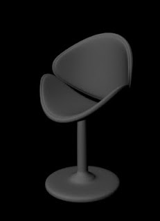
In this tutorial, you will create an arm chair using the polygon modeling techniques using Maya 2014, as shown in Figure t2-1.
 |
| Figure t2-1 The model of an arm chair |
Step -1
Start a new scene in Maya 2014.
Step -2
Choose Create > Polygon Primitives > Cylinder > Option Box from the menubar; the Tool Settings (Polygon Cylinder Tool) window is displayed in the viewport, enter 10, 2 and 1 in the Axis divisions, Height divisions and Cap divisions edit boxes, respectively, as shown in Figure t2-2.
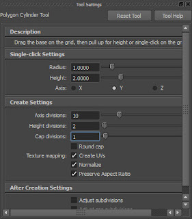 |
Figure t2-2 The Tool Settings (Polygon
Cylinder Tool) window |
Step -3
Click on the viewport; pCylinder1 is displayed in it, as shown in Figure t2-3.
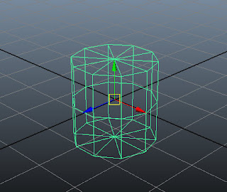 |
| Figure t2-3 The cylinder displayed in the viewport |
Step - 4
Choose Shading > Smooth Shade All from the Panel menu or press 5; pCylinder1 is displayed in the shaded mode.
Step - 5
Rename pCylinder1 as base in the Channel Box / Layer Editor.
Step - 6
Hover the cursor on the persp viewport and then press SPACEBAR; the four viewports are displayed. Next, maximize the front viewport.
Step - 7
Select base. Next, choose Scale Tool from the tool box or press R.
Step - 8
Uniformly scale down the base, as shown in Figure t2-4.
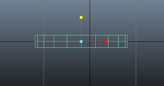 |
| Figure t2-4 Base scaled down |
Step - 9
Hover the cursor on the front viewport and then press SPACEBAR; the four viewports are displayed. Maximize the persp viewport.
Step - 10
In the persp viewport, press and hold the right mouse button on base; a marking menu is displayed. Next, choose Face from the marking menu.
Step - 11
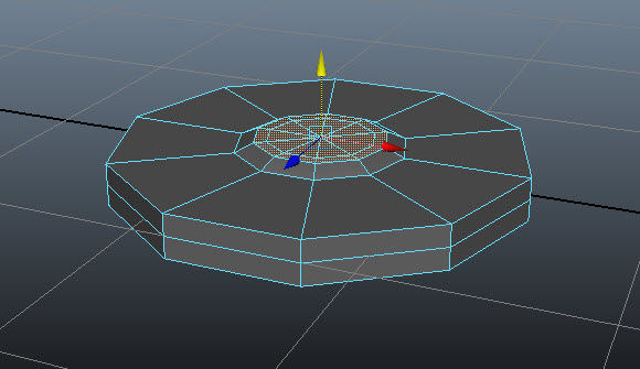
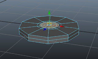
Now, select the top faces of base using the SHIFT key, as shown in Figure t2-5. Next, choose Edit Mesh > Extrude from the menubar.
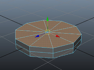 |
| Figure t2-5 Top faces of the base selected |
Step - 12
Invoke Scale Tool and scale down the selected faces uniformly, as shown in Figure t2-6.
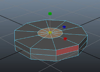 |
Figure t2-6 The top faces of the base
scaled down uniformly |
Step - 13
Press G key to invoke the Extrude command again. Next, invoke the Scale Tool by pressing R key and then scale down the selected faces uniformly, as shown in Figure t2-7.
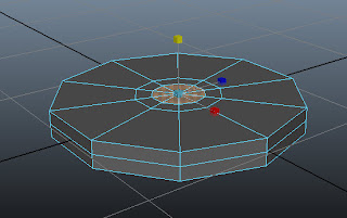 |
Figure t2-7 The selected faces of the base
scaled down uniformly |
Step - 14
Choose Edit Mesh > Insert Edge Loop Tool from the menubar. Next, click on top region of the base; an edge is inserted, refer Figure t2-8. Press W to deactivate the Insert Edge Loop Tool.
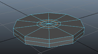 |
Figure t2-8 An edge inserted at the
top of the base |
Step - 15
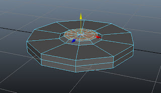
Press and hold the right mouse button; a marking menu is displayed. Next, choose Face from the marking menu. Select the faces of base using SHIFT, as shown in Figure t2-9.
 |
| Figure t2-9 Faces of the base selected |
Step - 16
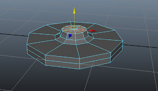
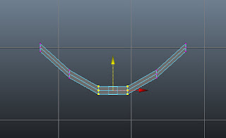
Next, move the seleced faces upward,
as shown in Figure t2-10.
 |
| Figure t2-10 Selected faces moved upward |
Step
- 17
Deselect the outer selected faces using
SHIFT and then move upward, as shown in Figure t2-11.
 |
| Figure t2-11 Outer faces moved upward |
Step - 18
Hover the cursor on the persp viewport. Press SPACEBAR; the four viewports are displayed. Maximize the
front viewport.
Step
- 19
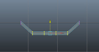
Press 5 to switch to the shaded mode. Choose Edit Mesh > Extrude from
the menubar. Next, invoke Move Tool and
then move the extruded faces upward, as shown in Figure t2-12.
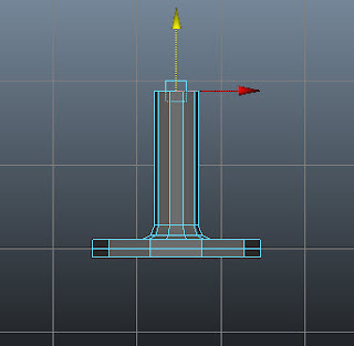 |
Figure t2-12 Extruded faces moved upward
|
Step -20
Press and hold the right mouse button
on base; a marking menu is displayed. Next, choose Object Mode and then select the base.
Step - 21
Make sure base is selected in the front viewport. Choose Mesh > Smooth > Option Box from the
menubar; the Smooth Options dialog
box is displayed. In this dialog box, make sure the Division
levels slider is set to 2. Now, choose the Smooth button; the geometry of base is smoothened, as shown in
Figure t2-13.
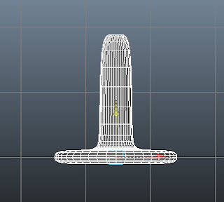 |
Figure t2-13 The smooth base displayed
|
Step - 22
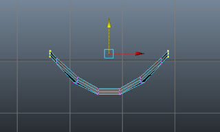
Press and hold the right mouse button on the base; a marking menu is displayed. Next, choose vertex from
the marking menu and then select the vertices, as shown in Figure t2-14.
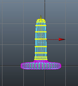 |
| Figure t2-14 Vertices selected |
Step - 23
Next, invoke the Scale Tool by pressing R
key and scale the selected faces uniformly, as shown in Figure t2-15.
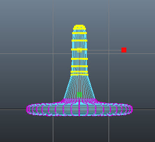 |
| Figure t2-15 Selected vertices scaled uniformly |
Step - 24
Now, scale the selected vertices downward, as shown in Figure t2-16. Switch to the object mode.
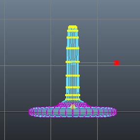 |
| Figure t2-16 Selected vertices scaled downward |
Step - 25
Hover the cursor on the front viewport. Press SPACEBAR; the four viewports are displayed. Maximize the persp viewport. Next, choose Create > Polygon Primitives > Cube > Option Box from the menubar; the Tool Settings (Polygon Cube Tool) window is displayed in the viewport, enter 5, 2 and 3 in the Width divisions, Height divisions and Depth divisions edit boxes, respectively, as shown in Figure t2-17. Next, enter 1,0.5 and 0.5 in the Width, Height and Depth edit boxes, respectively, refer to Figure t2-17.
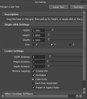 |
Figure t2-17 The Tool Settings (Polygon
Cylinder Tool) window |
Step - 26
Click on the persp viewport; pCube1 is displayed in the viewport, as shown in Figure t2-18.
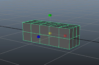 |
| Figure t2-18 The cube displayed in the viewport |
Step - 27
Rename pCube1 as seat in the Channel Box / Layer Editor.
Step - 28
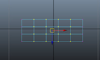
Maximize the front viewport. Scale the seat along the X and Y axis, as shown in Figure t2-19.
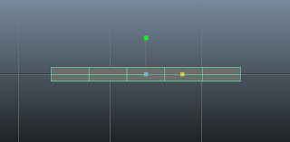 |
| Figure t2-19 The scaled seat |
Step - 29
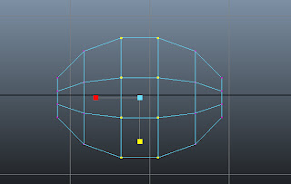
Press and hold the right mouse button on it; a marking menu is displayed. Choose vertex from the marking menu. Now, select the vertices, as shown in Figure t2-20.
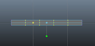 |
| Figure t2-20 Vertices to be selected |
Step - 30
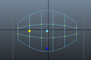
Choose the Move Tool. Now, adjust the selected vertices, as shown in Figure t2-21.
 |
| Figure t2-21 Selected vertices adjusted |
Step - 31
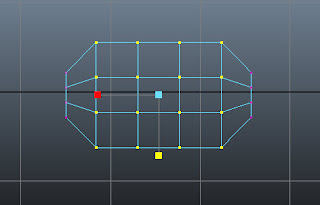
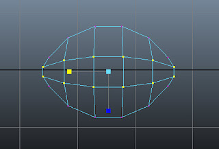
Similarly, adjust other vertices to create the basic shape of seat, as shown in Figure t2-22
 |
| Figure t2-22 Other vertices adjusted |
Step - 32
Maximize the top viewport and then select the vertices as shown in Figure t2-23a. Choose Scale Tool and then scale the selected vertices along the Z-axis, as shown in Figure t2-23b.
 |
| Figure t2-23a The vertices to be selected |
 |
| Figure t2-23b The selected vertices scaled |
Step - 33
Similarly, scale other vertices, as shown in Figure t2-24.
 |
| Figure t2-24 Other selected vertices scaled down |
Step - 34
Select the vertices, as shown in Figure t2-25a. Next, scale the selected vertices along the X-axis, as shown in Figure t2-25b.
 |
| Figure t2-25a Vertices to be selected |
 |
| Figure t2-25b New selected vertices scaled left |
Step - 35
Maximize front viewport. Choose the Move Tool. Now, select the vertices, as shown in Figure t2-26a and then adjust the selected vertices, as shown in Figure t2-26b.
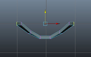 |
| Figure t2-26a Vertices to be selected |
 |
| Figure t2-26b Selected vertices adjusted |
Step - 36
Press and hold the right mouse button on it; a marking menu is displayed. Next, choose Object Mode from the marking menu and then select seat.
Step - 37
Choose Mesh > Smooth from the menubar; the mesh of seat is smoothened.
Figure t2-27 shows the seat after smoothing.
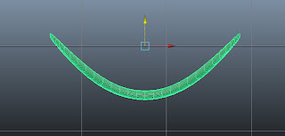 |
| Figure t2-27 The smooth seat displayed |
Step - 38
Next, press CTRL + D; a duplicate copy of the seat is created with the name seat1 in the viewport.
Step - 39
Choose Rotate Tool from the Tool Box or press E. Now, enter 90 in the Rotate X edit box in the Channel Box/Layer Editor; seat1 is rotated 90 degrees about the X-axis.
Step - 40
Next, choose the Move Tool and then align seat1 in all viewports, as shown in Figure t2-28.
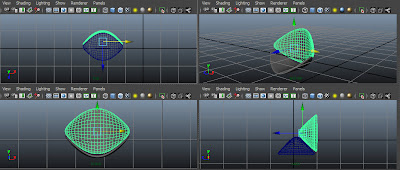 |
| Figure t2-28 Copied object aligned in all viewports |
Maximise the persp viewport. Choose Render the current frame button from the status line to view the output, refer to Figure t2-32.
 |
| Figure t2-32 The rendered model of the arm chair |